Manufacturing and design engineers in nearly every major industry—from automotive to power generation and from space to healthcare—recognize the direct relationship between system cleanliness and system performance. Providing adequate system filtration to remove fine particles and to offer last-chance protection against large foreign object debris is typically the responsibility of the designer. In this article, learn why it is essential to protect system components for their entire operating lifecycle. This article will describe various types of contamination, walk you through some common signs of trouble, showcase two real-world contamination examples captured in photographs, introduce you to a few solutions, and provide you with basic tips on comparing screens.
At The Lee Company, we understand performance means everything. For over 75 years, thousands of Lee components have played a vital role in fluidic system performance for a wide range of aerospace, automotive, medical, and industrial applications in systems designed to withstand a variety of fluid contamination scenarios. Our experience has helped us gain insight into how contamination can be introduced in a system. Contamination can result from built-in factors that are ultimately traced back to the manufacturing process; contamination can be introduced through service in the field; contamination might be related to poor chemical compatibility between the fluid and components; and finally, contamination may also be caused by the sudden, prolonged, or even normal and otherwise ordinary wear of moving components.
In addition to small issues such as minor leaks or slightly reduced flow, contamination may also result in serious consequences for both the system and the related business, including:
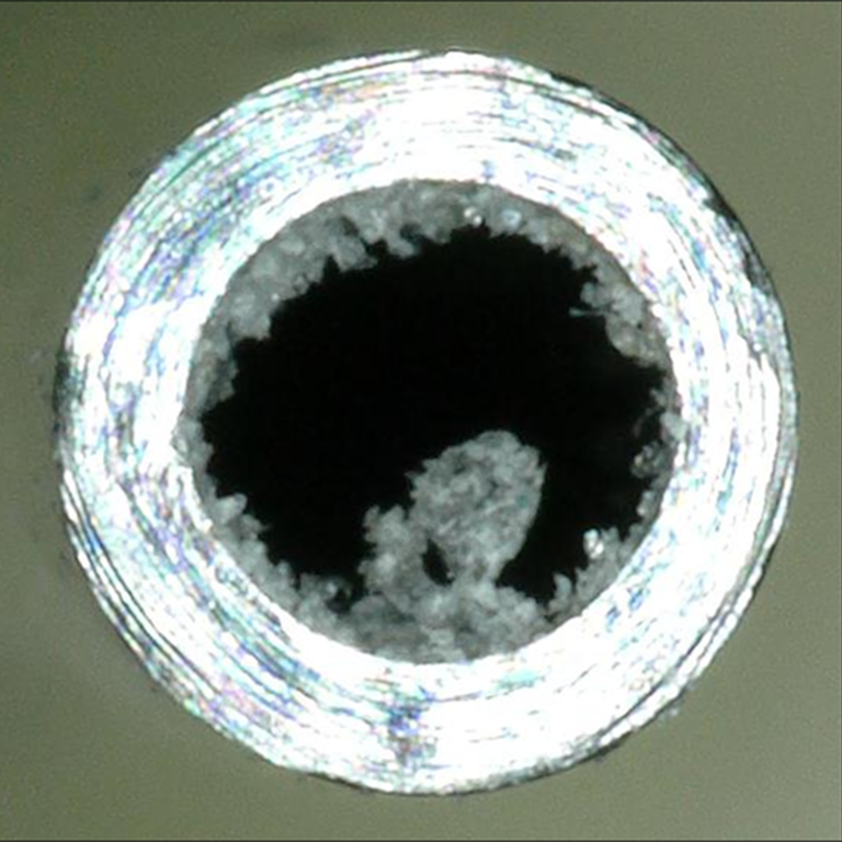
Below: A common example of contamination in a small stainless-steel hypo tube used as the port on a manifold. Flexible tubing is typically pressed over the hypo tube to connect the manifold to other components in the system. The area inside the tube exhibits significant crystal growth—a type of contamination that is self-generated inside the system and not externally introduced. As crystals form, the inside diameter of the tube is reduced, restricting the effective flow volume supported by the tube, and increasing the pressure that is required to achieve the same flow. Depending on system design, some growth may go unnoticed for a time; however, the contaminant continues to gradually reduce system performance and will eventually block the flow. A secondary concern is that the mass in the center is large and unsupported. Fluid could break it off and carry it downstream where it would likely encounter a restriction, such as a nozzle, and perhaps result in a clog. If that particulate is upstream in proximity to a valve, it might lodge on the valve seat and create a leak path.
 In these situations, costs are increasing while customer satisfaction and revenue are declining. The Lee Company is a leading authority on identifying and preventing these notorious customer pain points.
How will you know when you have a potential contamination problem? You might notice reduced pressure or slowed response times. Contamination can cause a variety of undesirable operating conditions. A partially clogged orifice may cause sluggish movements within an actuator. The inability to maintain pressure in a reservoir during charging could be due to leakage caused by a piece of contamination caught between a fill valve poppet and seat. Contamination should always be taken into consideration as a possible cause whenever a system is not operating at the desired peak performance.
Even with small amounts of contamination, fluid behavior may be compromised. In some cases, smaller size contaminants may not cause an immediate threat to a system or its components, but over time, this contamination could build up and form a sludge on the walls of the reservoir. This sludge formation can be detrimental to the system as it decreases the efficiency of heat transfer in the reservoir, resulting in higher system temperatures.
Debris, chips, and rogue particles are other sources of contamination. For example, if the primary machining operation on a transmission manifold is not flushed and cleaned properly, it can leave behind metallic chips. These chips are then able to flow throughout the system and can potentially damage other components, lower the performance of the system, or cause it to fail completely. Similar contamination is sometimes found in supply lines and castings in the form of small particulates or burrs that can sometimes break loose and damage downstream components.
Crystallization is a self-generated form of contamination that can result in downstream issues over time. System designers must take precautions when using fluids that may be prone to crystallization within valves or other components. Allowing the fluid to dry or neglecting to adequately flush the system when it will be shut down or idle for extended periods of time can result in the formation of crystal buildup, a common cause of performance issues. Medical device applications represent a common industry for this type of contamination. For example, consider a diagnostic instrument that uses chemistry to perform a given analytical test. If an upstream restriction results in reduced flow, this condition could impact throughput and, more importantly, the accuracy of the test.
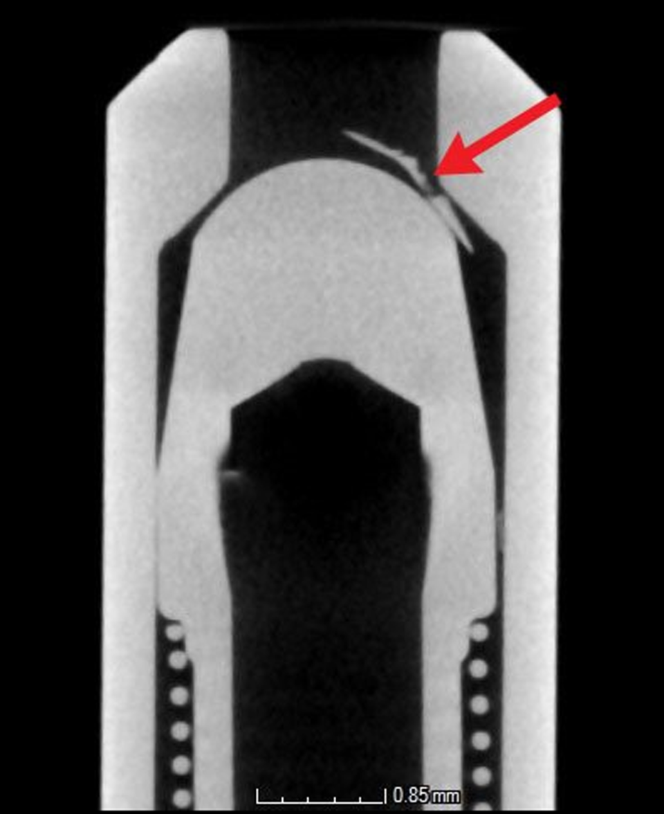
Below: An image from The Lee Company’s CT scanner showing that contamination is preventing the poppet of this valve from making clean contact with its seat. As a result, the valve cannot form a seal and does not close properly. Contaminants in sensitive sealing areas such as this could block components from sealing completely, and, in turn, could contribute to leakage. In this example, the valve should be fully closed but is obstructed.
What is difficult for many of us to admit is that even when we practice the proper manufacturer-recommended maintenance during the break-in period for a machine or component, we are still exposed to contaminant risk factors.
You are probably familiar with some common instances of this paradox. For example, you might perform a recommended initial priming or flushing procedure for a gas or diesel generator during its first 20 hours of operation. This procedure helps to remove any built-in contamination introduced during the manufacturing process and the initial assembly of the unit. After this short break-in period followed by initial flushing of the oil system, it is generally acceptable to run the unit for a much longer period of time between flushes or further maintenance.
But just be aware that the onset of contamination has already begun. Each part in your system may contain some degree of built-in contamination, so when you assemble a system with a variety of components, some contamination will almost always result. For example, each component could contain dust from a worker’s benchtop, a loose burr as a result of a machining operation, or particulate added to a component when tested on a dirty test stand. During system operation, fixed components may offer a lower probability of introducing contamination but moving components such as meshing gears or sliding fits carry an increased risk for producing self-generated contamination. Although the system may be impervious to some degree of smaller contamination, it only takes one larger rogue particle to prevent a component from functioning properly.
Undetected rubbing, wear, and other internally generated friction can also result in impurities, surface fatigue, flexing, and stressing. Housing, tubing, connectors, and similar components are often subjected to additional stress and vibration which can also contribute to contamination. This contamination might manifest as particulates or even fluid loss. Over time, catastrophic failure can result.
Your own service personnel in the field can also be unknowingly introducing contamination. Anytime an overhaul is performed, there is always a chance for contamination to be introduced into the system. It may be a result of the simple threading and unthreading of fittings where metal-to-metal contact and galling may occur, potentially generating contamination. Some fittings might include a coating or plating as an integral part of their design; however, these protective layers are also subject to flaking, another source of contamination. Maintenance performed on-site or in an unclean environment also opens the possibility of exposure to contamination from the surroundings. After an overhaul operation is performed, fluids generally need to be replenished to bring their levels back to specification. Refilling fluids from unfiltered or rusted containers is also a frequent source of contamination from unwanted small debris.
Each part in your system may contain some degree of built-in contamination, so when you assemble a system with a variety of components, some contamination will almost always result.
To optimize system performance, it is critical to ensure that the system’s components are protected from contamination. The best method of protection depends on a variety of factors, including the types of contamination that might be present and the location of critical components in your system. Below is an overview of factors that system designers should consider when determining the best method of protection against rouge debris in a system:
Examine your components and consider their location. Components that are close to the system filter may need less protection than a similar component that is just downstream of a gearbox or pump, where the likelihood of generating contamination is greater due to moving parts. Regardless, the secondary screen should be placed as close as possible to the critical component that it is protecting. This may mean designing a screen into a critical flow part (for example, a screen placed at the inlet of an actuator) or installing the screen directly onto the critical component that it is protecting (such as a check valve or orifice with an integral screen).
The size of the contaminants in each system is going to influence your decisions about how you go about developing a protection plan for each orifice, relief valve, and other potentially sensitive hydraulic components. Even among your most critical components, low levels of relatively small particulates might not make the shortlist of concerns. But a single large particle can cause sudden catastrophic failure. For components with tight clearances less than 0.070 of an inch (<1.78 mm), secondary screening should be considered for additional protection. The screen hole size should be based on the minimum orifice diameter or passage sizes, such as a valve opening or clearance. Choose a safety screen hole size that is generally between 30 to 70% of the minimum passage size.
As mentioned above, a certain amount of contamination is inevitable. Solutions often focus on system filtration and the location of critical flow components. A system filter provides fine filtration and helps to maintain a degree of fluid cleanliness for the entire system. Most often, a single filter is used, but some systems have several located throughout the circuit. Often, sensitive components are located far from the system filter, leaving them with little protection against larger contaminants. Large particles can cause a component failure such as blocking a flow restrictor or holding open a check valve. These failures can result in extensive and costly downtime. Last chance safety screens are designed to provide an additional level of protection against these rogue particles that may be built-in or generated downstream of the system filter.
We recommend that you plan for the installation and replacement of safety screens. You can rely on filters to maintain fluid cleanliness when your operation is exposed to smaller contaminants; however, mature systems and critical components require a different approach because of the inherent large built-in risks that grow more and more serious with each hour of operation. For added levels of protection, you will need to invest in safety screens.
“The size of the contaminants in each system is going to influence your decisions about how you go about developing a protection plan.”
For added protection, include safety screens in your system design and maintenance plans. Even if your system was miraculously free of debris prior to manufacturing, you flushed all components and handled each part with care prior to installation, and you arranged for proper system filtration, you cannot guarantee that rogue debris or contamination will not appear and cause harm within your fluidic system. Therefore, safety screens located just upstream of critical components are the preferred method to provide protection, eliminate risk, and guarantee performance in critical applications.
Screen performance is generally characterized by ensuring it filters the appropriate debris, minimizes the restriction it creates within the system to the fluid passing through it and is able to withstand the system and environmental pressures it will be subject to over its life. There are many different options when selecting a safety screen that will impact its performance. Some examples include the method of construction, material, geometry, and the number and dimensions of the holes in the screen. Depending on the application and the number of variations, comparing two safety screens may be difficult. However, there are a few ways to compare similar safety screens.
Comparing Screens Using Open Area
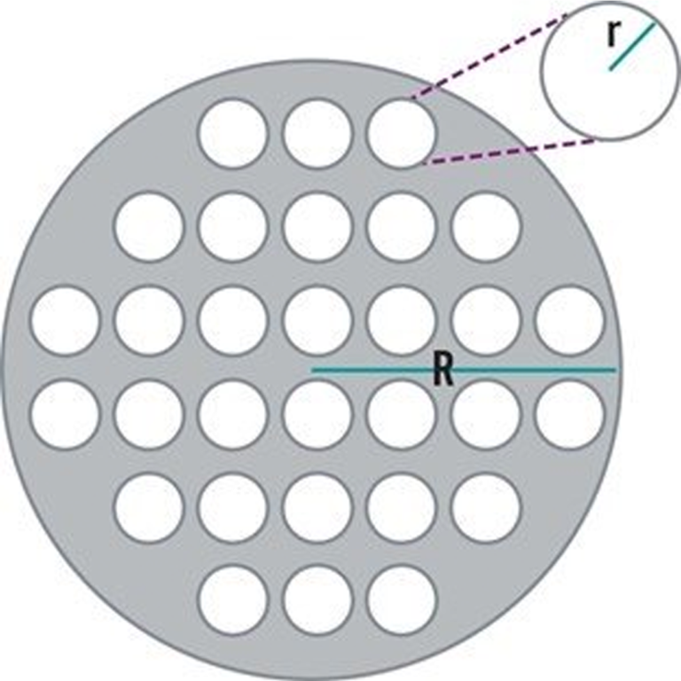
The term open area represents a useful measure of contamination holding capacity. When comparing screens of similar hole sizes, the open area gives a quick indication of the dirt holding capacity of one design versus another. It is simply the product of the number of holes (N) times the area of a nominal hole:
Open Area = N × 𝜋r2
The ratio of open area to total area is known as the percent open area.
% Open Area = (N × 𝜋r2) / 𝜋R2
Open area calculations only provide a quality comparison between screens with similar hole sizes and geometries. Historically, dissimilar screens had to be compared through expensive testing. Fortunately, to compare screens with different hole sizes, The Lee Company developed the Resistance to Blockage (ROB) number, a system of rating the relative resistance to blockage of safety screens.
ROB numbers provide a reliable means of comparing one screen design to another. The ROB number was conceived to aid system designers in choosing the optimum screen for their applications relative to the other screen options available.
The ROB number system is based on the following assumptions:
The same contamination level applies to all screen options.
Fluid contamination level is not affected by having a safety screen in the system.
When particles block holes, the way they block different size holes is essentially the same.
Particle distribution follows a log – log2 distribution.
A fluid contamination level per MIL-STD-1246 Class 200 was chosen as the basis of comparison with the ROB Number defined as:
Rob = N /63.25n
where n = 10(4.9029 – 0.926 log2d)
d = hole size (µ)
N = # of holes in the screen
To learn more about controlling contamination, safety screen technology, or ROB numbers, and other criteria necessary to select proper filtration, contact your local Technical Sales Engineer or visit our website where additional resources are available to help you optimize your components, applications, and systems.


