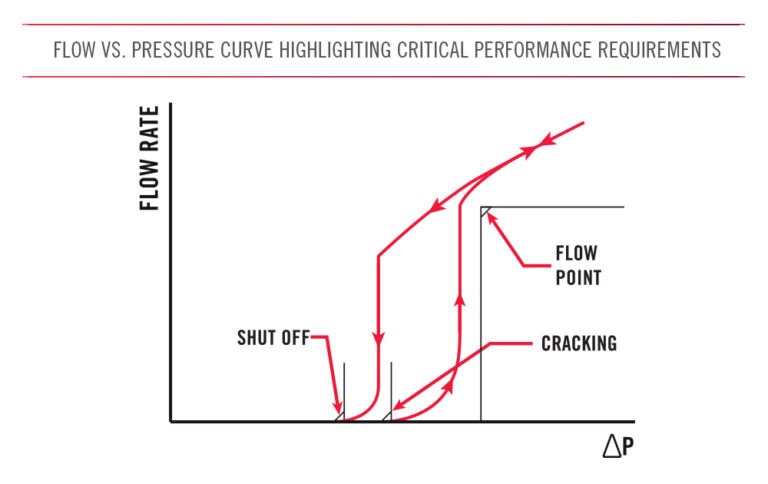
There are several factors that must be considered to ensure proper operation of a pressure relief valve within a system or pressure vessel. Neglecting to consider these factors can lead to reduced valve or system performance, damage to other components within the system, or a total system failure. The below chart highlights the critical performance points that are typically defined for a pressure relief valve. Further performance characteristics that should be considered when selecting a pressure relief valve are discussed below.
There are four pressure ratings that should be considered for any pressure relief valve: operating pressure, system pressure, proof pressure, and burst pressure. Operating pressures are the pressures the valve will be subject to during normal operation throughout its life, both in the relief flow direction and the checked, or opposite, direction. System pressure is the maximum nominal pressure that the system the valve is installed into will achieve. Proof pressure is the pressure the valve should be able to withstand without permanent deformation or degradation of performance when the system returns to operating pressure. Burst pressure is the pressure at which the valve should survive without rupturing or bursting. All four pressure ratings must be considered during design to ensure the valve and its components are durable enough for the application.
A pressure relief valve’s set pressure, or cracking pressure, is the pressure at which the valve opens and begins to allow fluid to pass. The cracking pressure is based on the pressure vessel or system’s design criteria and is typically defined as a nominal pressure with a tolerance or as a minimum. The minimum cracking pressure is the lowest pressure that the valve may open and implies the actual crack will occur at a pressure between the minimum and the relief flow pressure as pressure increases.
If the valve opens at a pressure that is too low, there is a risk of improper valve operation or a decrease in system efficiency. Alternately, if it does not crack open and pressure increases too much, there is a risk of experiencing the issues which the valve is supposed to prevent such as deformation to the system or its subcomponents. The flow curve on page 7 highlights the critical performance requirements, including cracking pressure, that are typically defined when selecting a pressure relief valve.
Use the Lee Product Finder to explore pressure relief valves by type, mounting configuration, diameter, and performance requirements.
To ensure that the system pressure does not reach a critical point, the relief valve must allow a certain volume of fluid to exit within a limited period of time. This flow rate is based on the potential rate of a pressure increase (also called a pressure rise rate), the volume of fluid in the system, and the volume of fluid that needs to be displaced to alleviate the pressure increase.
For example, a pressure relief valve protecting a large pressure vessel from damage due to a powerful pump malfunction requires more flow capacity than a pressure relief valve protecting a small pressure vessel from the pressure increase created by thermal expansion on a hot day.
The flow rate the valve is designed to achieve is typically defined at a specific pressure known as the flow point pressure, overpressure point, or relief flow pressure. The flow point pressure is always higher than the cracking pressure and may signify when the valve is in its fully open state, at which point it will perform as a fixed restriction. This performance criteria ensures the pressure relief valve will relieve enough fluid at a low enough pressure to prevent further increases in pressure or to reduce system pressure back to safe levels.
A pressure relief valve’s reseat pressure is the pressure at which the valve closes when decreasing from the open state. The shut off pressure is the pressure at which the valve completely shuts off and no longer allows excessive internal leakage past the valve’s seal. These pressures are typically defined as minimum pressures. These are the lowest pressures that the valve is allowed to close or stop leaking and implies the actual reseat or shut off will occur at a pressure between the relief flow pressure and the minimum as pressure decreases. The crack or overpressure points protect the vessel or system, while correctly specifying the reseat or shut off pressure ensures continued normal operation of the system. Like the cracking pressure, if a reseat or shut off pressure is too low, there is a risk of improper valve operation or a decrease in system efficiency.
Valve leakage can be broken down into two categories: external and internal. External leakage refers to fluid flowing around the exterior of the valve body, which may include threads, O-ring seals, or other external features. Internal leakage is any fluid flow through the valve’s body while the valve is in its closed position. Leakage allowances can be influenced by variables such as whether it is an open or closed system, total system volume, fluid transfer capability, and desired system efficiency.
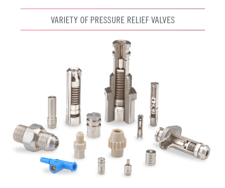
A pressure relief valve is comprised of several sub-components. The materials of each component must be able to withstand the various forces that will be applied to them during the valve’s operating life. This includes the pressures applied internally and externally to the valve, along with the associated pressure rise rates.
Materials must also be compatible with their environment, including external fluids, temperatures, and the system fluid that will relieve through the relief valve. It is possible that a valve may be subject to extreme humidity or be incorporated in a system submerged in other liquids or gases. The valve’s materials should be considered when determining how the valve will be installed into the system. Failure to consider material compatibility may create issues related to thermal expansion and corrosion.
The envelope is an important factor to consider when selecting a relief valve. The first consideration is the location of the valve within the system and the desired flow path for the relieved fluid. The system may require the relief valve to be located within a specific area, limiting external dimensions or overall size. The location may also dictate the flow path of the relieved fluid based on existing lines. The envelope must also account for installation, retention, and maintenance requirements. For example, some valves incorporate threaded fitting ends, while others are installed directly into manifold housings. Next, determine whether the installation must be permanent or removable. Finally, evaluate if the valve may be used in a system in which weight is a factor, such as a portable system or when fuel efficiency is paramount.
After determining the required performance characteristics of a relief valve, it is critical to identify other variables that will influence the pressure relief valve’s design. The internal and external environment of the system will affect the valve’s design in a variety of ways, impacting every aspect of its functionality and limiting options for the valve’s construction. When designing a valve, the following aspects of the system and environment must be considered:
The performance of a pressure relief valve is greatly affected by the operating fluid’s viscosity and specific gravity. Liquids and gases have different fluid properties that impact flow rate, leakage, and the movement of the valve’s internal components. The operating fluid also introduces other variables that must be considered, such as material compatibility. A fluid that is incompatible with the valve’s materials could cause damage to the valve, including corrosion or other harmful effects. This damage will negatively affect the performance of the
valve, and subsequently the system. It is also possible that the valve’s materials may alter the fluid’s properties, negatively affecting system performance. For example, a system analyzing blood or chemicals must use components that are inert to the fluid being analyzed. Similarly, a system flowing a flammable gas may need to avoid metals that may ignite when making contact.
It is important to consider how long the valve must withstand the conditions it will be exposed to during operation. This includes both the maximum length of time the valve shall be in service and the number of cycles the valve performs. A pressure relief valve may experience wear due to exposure to its environment or by forces caused by contact of internal components, particularly the sealing surfaces. Excessive wear of the valve’s components over an extended operating life could lead to performance issues.
Both the temperature of the fluid and the ambient temperature can impact the performance of a pressure relief valve. Changes to the temperature of the fluid will alter the fluid’s properties, including viscosity and specific gravity. Liquids will thicken and increase in density with decreases in temperature, making it harder for the fluid to flow. Conversely, increasing temperatures will cause the fluid to thin, lowering its viscosity and density. Maximum leakage rates may be higher as temperatures increase because leakage is more likely to occur when working with a thinner fluid. Temperatures also impact decisions about the materials used in the pressure relief valve. At cold temperatures, some materials become hard or brittle. At elevated temperatures, materials may become soft or melt. These changes can reduce a valve’s operating life. The minimum and maximum temperature rating should be specified for valve performance, normal operation, and survivability.
Relief valve performance is typically based on changes in pressure within the system or pressure vessel. However, the pressure relief valve envelope may be subject to other environmental pressures, such as those found deep underwater, underground, or even the absence of pressure found in outer space.
Pressure relief valves can be subject to forces external to the system in which it is installed, as well as the forces generated by operation of the system. These forces are typically vibration, shock, and G-forces. For example, some systems or vehicles which use pressure relief valves generate levels of vibration during normal operation. A shock may occur if the system or vehicle in which the valve is installed suddenly encounters another object. Lastly, the system or vehicle may generate G-forces during operation due to sudden or rotational movement.
The magnitude, frequency, and direction of the potential forces must be considered. The internal components of the valve move differently based on the direction of the force. The frequency of the vibration may be detrimental to the valve if it corresponds to the natural frequencies of the design. In most cases, a relief valve is required to withstand and even remain closed during these events.
A pressure relief valve may have trace amounts of fluids, debris, or dust on or within the valve. This contamination may be caused by the processes used to manufacture the valve or the environment it is subjected to during manufacturing, transportation, or storage. In most cases, the trace amount of contamination that is present on the valve at the completion of production is acceptable. If the end user cannot tolerate the presence of this level of contamination, the valve may need to go through special cleaning and packaging processes. Examples of these types of applications include a pressure relief valve used in a chemistry analyzer or in an oxygen system which provides breathable air to a person. Some industries, such as the space, automotive, and medical industries, have defined cleanliness levels that dicate these requirements for any component or system.
Safety relief valves are designed to achieve a specific flow rate when open at the flow point pressure. The system’s source of pressure, such as a pump, must be able to supply that minimum flow rate to the pressure relief valve while it is open, or else it may become unstable. It is also important that the flow path between the pressure source and the pressure relief valve does not include any restrictions or other components that will prevent the necessary flow from being supplied to the relief valve.
Always verify flow calculations by experiment.
*There are many parameters to consider when determining V-Factor. Click here for more information.


