


Sarah Charette
Technical Marketing Manager – Health & Science
Westbrook, CT
See Bio
A solenoid valve is an electromechanical device used to control the flow of a liquid or gas. It is comprised of two features: a solenoid and a valve. The solenoid is an electric coil with free-moving ferromagnetic material in the center of the coil, often referred to as a “plunger.” When voltage is applied to the coil, the solenoid is energized. This action creates a magnetic field that either attracts or repels the plunger and causes it to translate linearly (see Figure 1).
The movement of the plunger alters the position of the components within the valve body to control the specific flow, direction, and pressure of fluid moving through the valve. When current or voltage is removed from the coil, the magnetic field collapses and all internal elements return to their de-energized position.
Solenoid valves are a part of everyday life. They control the flow of water in dishwashers, the flow of propane to ignite a
gas stove top, and even the flow of fuel in a car engine. These valves are available in a wide range of configurations depending on the system in which they are used and their intended function.
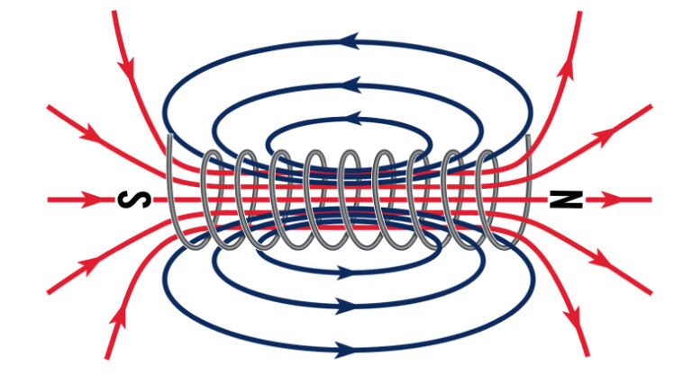
Figure 1: Electrical Field Through Solenoid Coil
Solenoid valves are used in a near infinite number of applications – from automatic sprinkler systems and inkjet printing to medical devices and satellite propulsion. Generally, their associated functions can be divided into four categories: open and close flow, control flow direction, control flow volume, and regulate flow rate.
The most common function for a solenoid valve is to open and close a flow path. For example, a solenoid valve in a dishwasher will be in the closed position when the dishwasher is off in order to conserve water. When the dishwasher is turned on, the valve will open for the period of operation during which water needs to flow onto the kitchenware.
A solenoid valve may also be used to control the flow path or direction that a fluid travels. When used for this purpose, the solenoid valve will typically have multiple inlet or outlet ports. Energizing the coil helps to change which ports are open so that the fluid travels through an alternate channel. For example, the valve can be used to mix two fluids together in a specific ratio. In this scenario, the valve will have two inlet ports, or one for each fluid. The outlet port will be connected to the mixing chamber. When the valve is de-energized, fluid “A” will travel into the mixing chamber. When the valve is energized, fluid “B” will travel into the chamber. The ratio of each fluid can be altered by varying the length of time that the valve is energized.
When precise flow volume is required, a solenoid valve may be operated to open and close during defined periods of time to allow a specified volume of fluid to flow through the valve. In printers, for example, a solenoid valve can be used to dispense droplets of ink. In these systems, the inlet pressure must remain constant to ensure that the flow volume over a period of time is consistent. When a high degree of accuracy is needed, other factors such as fluid properties and environmental conditions can also impact flow rate.
A solenoid valve can function to control the flow rate of a liquid. When used for this purpose, the valve may be able to operate quickly enough that varying the frequency at which the valve is energized also varies flow rate through the valve body. This technique is commonly referred to as Pulse Width Modulation (PWM). Solenoid valves can also be designed to operate in a non-binary position in which the valve is neither fully open nor fully closed. These valves are commonly called proportional valves. By adjusting the valve components, overall restriction of the valve changes and meters flow. For instance, oxygen concentrators use solenoid valves to vary the flow rate of oxygen to a patient based on an individual’s need.
Use the Lee Product Finder to explore solenoid valves by configuration, porting, actuation type, and performance requirements.
A basic solenoid valve is comprised of a number of components, which are described below.
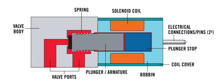
Figure 2: Basic Solenoid Valve Components
Figure 2 shows a solenoid valve configuration in a de-energized state. When energized, the solenoid coil will pull the plunger towards the plunger stop with enough force to overcome the spring and open flow between the two ports.
Solenoid Valve Configurations and Design Considerations
Since solenoid valves are used in a wide range of applications, there are boundless configuration possibilities available. Choosing the appropriate configuration is largely dependent on the valve’s intended use within a system or environment. After all, a solenoid valve that controls liters of hydrogen at cryogenic temperatures has very little in common with one helping to move nanoliters of blood in a laboratory. There are design options available for some of the most basic features of a solenoid valve. Choosing between these options will help to shape the valve’s eventual configuration.
Number of Valve Ports
Solenoids may control fluid travel between two, three, or even four valve ports.
A 2-port valve, or 2-way valve (also known as a “2/2 solenoid valve”), is the simplest design (see Figure 3). They may serve the on-off function or regulate flow. The ports may be labeled as inlet and outlet ports, however, if the valve is bi-directional, they may just be referred to as Port A and Port B or some other descriptor based on the function of the valve.
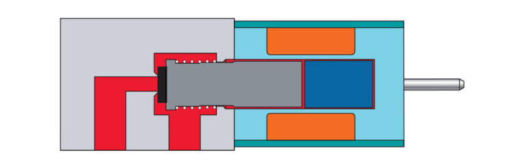
Figure 3: 2-Port Valve, or 2-Way Valve Configuration
A 3-port valve is typically a 2-position, 3-way design (see Figure 4). It is often referred to in shorthand as a “3/2 solenoid valve,” which refers to the valve’s three port/two position design. This means that in the de-energized state, two of the ports are connected. When energized, the valve transitions. During this time, one of the ports is closed and the other opens to the third port. In this case, the port that is always connected may be referred to as the “common port.” The other ports may be referred to as “normally open” (open when coil is de-energized) and “normally closed” (open when coil is energized).
A 3-port solenoid valve (3/2 way solenoid valve) can function in three different ways:
Figure 4: 3-Port Valve Configuration
In a two-position, 4-way valve (also known as a “4/2 way solenoid valve”), switching the valve changes which two ports connect to one another. The animated image below illustrates how the valve can transition between the first, second, and third positions to alter the connected port pairing (Figure 5). In one position, port one (P1) and port two (P2) are connected, and ports three (P3) and four (P4) are connected. In the second position, all flow is closed off. In the third position, port one connects with port four and port two connects with port three.
Valves are often referred to as normally open (NO) or normally closed (NC). This is a common differentiation for 2-port valves and is sometimes used to distinguish between similar multi-port designs. These terms refer to the de-energized position of the solenoid valve: either closed or open. In a normally closed configuration, the spring holds the valve seal against the seat to prevent flow when the coil is de-energized. When energized, the valve opens. In a normally open configuration, the spring holds the valve seal away from the seat to enable flow when the coil is de-energized. Energizing the coil shuts off flow.
To help improve power consumption, a user may opt for a solenoid valve that stays most often in a de-energized state. In some cases, however, the system benefits more if the valve is in the less common state if a loss of power occurs. A valve that is commonly open to allow a pressure source to operate a system, for example, may want to close in the event of a power loss to maintain upstream pressure and functionality.
In a direct-acting design, the moving plunger mechanism relies on power from the coil to directly open and close the seal against the valve seat. In pilot-operated designs, the plunger’s movement allows other components to move and transition in order to open and close the valve. Pilot-operated designs are common in applications where higher flow is required.
Many solenoid valves are referred to as either “pressure to close” or “pressure to open” designs. In a pressure to open valve, pressure at the valve’s inlet acts to move or keep the valve in the open position. In a pressure to close design, pressure at the valve inlet acts to move or keep the valve in the closed position. In piloting designs, this may be important to ensure proper transition of valve components under varying conditions. It can also be critical if there is a desired valve position in the event that other forces commonly acting on the solenoid valve fail to operate (such as the spring or solenoid coil).
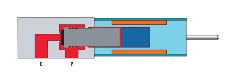
Figure 6: Pressure Assist to Close
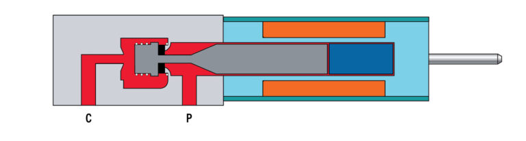
Figure 7: Pressure Assist to Open
Solenoid valves can be manufactured with a single coil or with multiple coils. This provides redundant control in the event of a failure. If each coil is controlled by a separate power source, one of the sources, drive circuits, wires, or coils can fail and the solenoid valve will continue to operate through the alternate coil. This may be necessary in critical applications, such as a solenoid valve used to operate the braking system of an airplane.
In a conventional solenoid, valve components are in one position when the coil is de-energized. The valve switches positions when the coil is energized, then returns to its original position when the coil becomes de-energized again.
Some solenoid valves operate using a latching solenoid design. In this design, the valve is energized momentarily to change positions but then remains in the new state even when the coil is de-energized. The valve will return to its original state only when directed to with a second signal. Latching valves offer many benefits and are often used in applications where power is limited. They provide additional advantage in applications when it is beneficial for the valve to remain in its current state in the event of an electrical failure, or when the valve would otherwise be energized for a length of time that could cause the valve to overheat.
There are two common types of latching solenoids: those held in place by a mechanical feature and those that are magnetically latched. In a mechanically latched valve, the mechanical feature needs to release or be disabled in such a way to allow the valve to return to its original position (such as a manual reset feature).
A magnetically latched solenoid valve contains a permanent magnet with a fixed polarization. The solenoid is operated using a drive circuit that allows it to reverse polarity of the solenoid coil, which reverses both the current direction within the solenoid coil and the magnetic field. By reversing the magnetic field from positive to negative, the plunger will be attracted or repelled from the permanent magnet. After a momentary pulse of electrical current sufficient to change the magnetic field and the position of the valve, the current can be removed, and the magnet will hold the valve in its existing position.
It is also possible for a solenoid valve to be designed with special internal features that allow residual magnetism from the voltage to provide sufficient latching force for the valve to remain in its current state even without a magnet. This scenario offers the same benefits as a magnetically latched design, without the need for the permanent magnet.
BROWSE OUR SOLENOID VALVES WITH THE LEE PRODUCT FINDER TOOL
The Lee Company designs and manufactures a wide range of valves from miniature plastic pneumatic solenoid valves intended for respiratory therapy applications to high pressure high temperature hydraulic solenoid valves operating miles underground in oil wells. If you are searching for a valve to meet your needs and would like to learn more about solenoid valves offered by The Lee Company, click here or contact a Lee Sales Engineer today.
If you want to learn more solenoid basics, view our related insights below.
Sarah Charette is the Technical Marketing Manager – Health & Science at The Lee Company. In this business development role, she draws upon her extensive engineering knowledge and market expertise to support the diagnostics, medical equipment, and scientific instruments industries. Sarah facilitates the creation of promotional content and product literature and provides technical and market-based training for a global team of sales engineers. She also manages customer relationships and acts as an internal liaison to the Lee product development team, coordinating product design and providing input for new components. She has been with The Lee Company for over 14 years, previously serving as a Product Manager for the Control Valve Group and Applications Engineer. Sarah received a degree in biomedical engineering and Spanish from the University of Rhode Island’s International Engineering Program and an MBA from Quinnipiac University.
Tom Cleveland is the Group Lead Engineer for the Solenoid Group at The Lee Company, where he works closely with sales and manufacturing on new and existing components and applications across multiple industries. In this role, he helps manage, train, and support Product and Project Engineers and provided expert guidance on major customer projects. Tom has been with The Lee Company for 13 years. He received a degree in physics and astronomy from Wesleyan University and a master’s degree in mechanical engineering from the University of New Haven.
Mathew French is the Technical Marketing Manager – Aerospace & Energy at The Lee Company. In this role, he manages customer relationships, leveraging his engineering and market knowledge to help identify business and product opportunities to support the aerospace and defense, space, oil and gas, motorsports, and power generation industries. Mathew oversees the creation of promotional material and educational assets and liaises with the Lee product development team to coordinate custom component design and offer feedback on new products. He also provides product and market training to The Lee Company’s global team of field sales engineers. Mathew has been with The Lee Company for over 19 years, previously serving as a Product Manager for the Solenoid Group and Applications Engineer. He received his mechanical engineering degree from the University of New Hampshire.
Always verify flow calculations by experiment.
*There are many parameters to consider when determining V-Factor. Click here for more information.