A flow restrictor is any device that restricts or limits the flow of a fluid—generally a liquid or a gas. Such devices may also be referred to as flow limiters. Calibrated orifices are one example of flow restrictors. They are used in systems we encounter daily. For example, they control how fast water flows from a faucet, how quickly foam sprays from a bottle of carpet cleaner, and how much fuel is flowing into the engine of a car.
Engineers tasked with managing fluid flow may refer to holes and to calibrated orifices, two very distinct entities. A hole can be any opening; a calibrated orifice is specially designed to precisely control fluid flow, and its diameter, length, and geometry are critical to its intended operation. With the proper design, an orifice can provide the desired control of fluid flow rates and pressure spikes.
When a fluid, either liquid or gaseous, passes through an orifice, its pressure increases upstream of the orifice. As the fluid is forced to converge and pass through the orifice, the velocity increases, and the fluid pressure decreases. This occurrence is based on the principle of conservation of energy. It is used to derive Bernoulli’s equation, which is discussed in greater detail in the Flow Equations portion of this eBook.
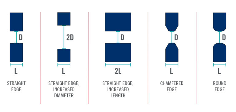
A calibrated orifice is the most basic flow restrictor. Orifice diameter, length, and geometry all impact the restriction of the orifice. As the diameter is increased, the amount of restriction decreases. As the length of an orifice increases, the amount of restriction increases. Two orifices with identical lengths and diameters may have a wide flow variation based on an orifice’s geometry. For instance, an orifice with a sharp-edged entrance results in a lower flow rate than one with a chamfered or radiused edge. In addition to flow rate, the geometry of an orifice can be used to create specific fluid behavior: for example, spin the fluid to help generate an atomized, conical spray pattern or focus the fluid on hitting a specific target point.
Use the Lee Product Finder to save time and streamline your design process with fast and accurate flow restrictor selection.
There are several restrictor configurations applied in industry today. The selected configurations are determined by the performance characteristics required of the system, ranging from simple to complex. A simple configuration may be a single orifice restrictor used in a system to reduce the acceleration of a cylinder. A more complicated configuration may be a multi-orifice design used to help reduce pump cavitation or protect sensitive components from system pressure spikes. Each configuration has some limitations that restrict or preclude its use in a particular system.
The most basic flow restrictor is a single orifice plate; it is highly adaptable, low cost, and widely used in controlling liquid and gas flow rates. The orifice plate can be attached to a housing in various ways for retention. The orifice designer varies the diameter, length, and geometry of the orifice to create the desired restriction.
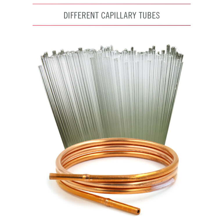
A single orifice may have to be very small to achieve extremely high restriction levels. Such small orifices are susceptible to clogging from contamination or debris. Engineers have created capillary tubes to increase the size of the minimum passage. Friction caused by fluid viscosity creates a pressure drop as the fluid passes through the capillary tube.
Capillary tubes are, therefore, unique compared to a single orifice restrictor; they will not behave the same in a dynamic system or when fluid properties change. The restriction can be increased or decreased by varying the tube length. Glass capillary tubes are commonly used in medical devices, and copper capillary tubes are typically used in refrigerators and air conditioners. The disadvantage of using a capillary tube is that it must be much larger than a single orifice plate to create the same restriction.
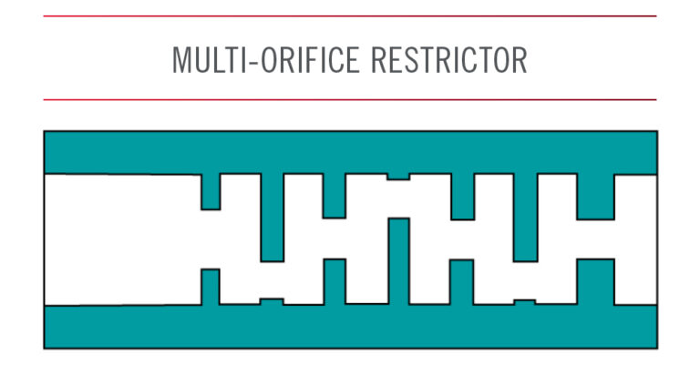
A flow restrictor may employ multiple orifices in series to increase the total combined restriction. Similar to using a capillary tube, a device may have a larger minimum passage size for an equivalent restriction than a single orifice device. A multi-orifice device may use orifices offset from one another to create a more rigorous flow path and further increase the restriction.
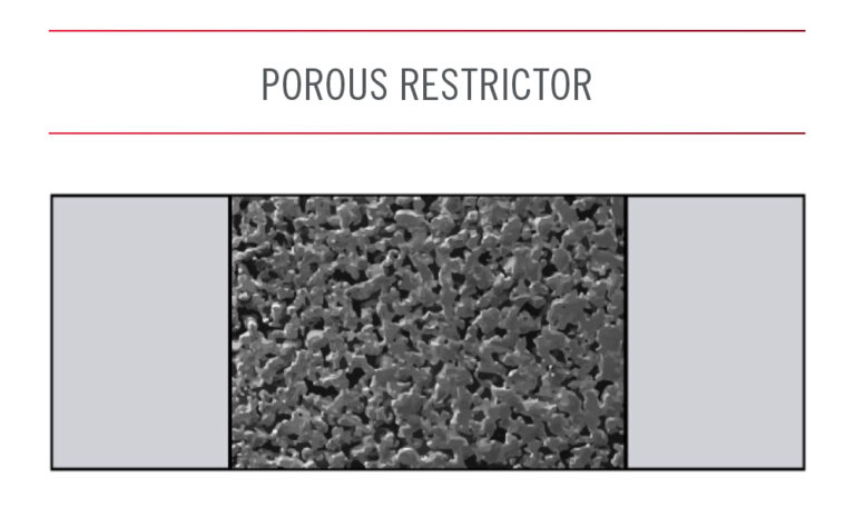
Some flow restrictors use a porous element rather than an orifice plate. The porous elements are often manufactured through a sintering process. As with a multi-orifice restrictor, the sintering process enables the device to provide a higher level of restriction in a relatively small package. The fluid can travel through multiple paths in series and parallel, making the device less likely to clog from a single piece of rogue contamination. However, due to the number of flow pathways, the minimum passage size through individual orifices may be smaller than that of a comparable single-orifice flow restrictor. In most cases, a porous restrictor element is also less economical to manufacture than a single orifice plate that would create the same level of restriction.
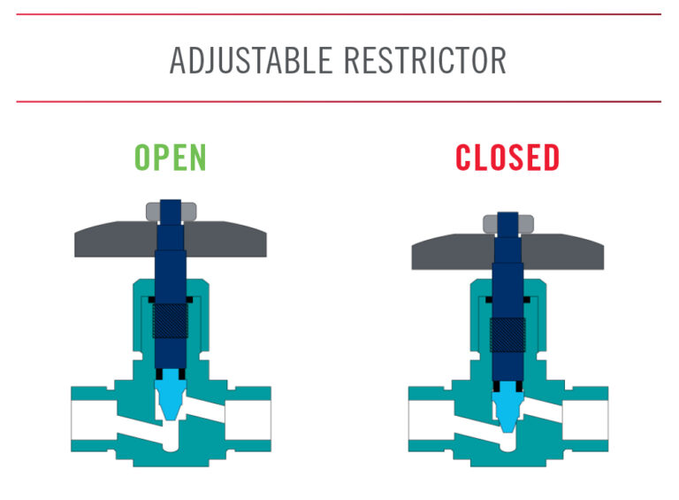
Flow restrictors may include a moving component that can be manually or electrically adjusted to change the flow restriction; the user can tune the flow restrictor to the optimal level as needed. Flow restrictors are intended to adjust the flow regularly; others may be tuned to a certain flow rate and then set permanently.
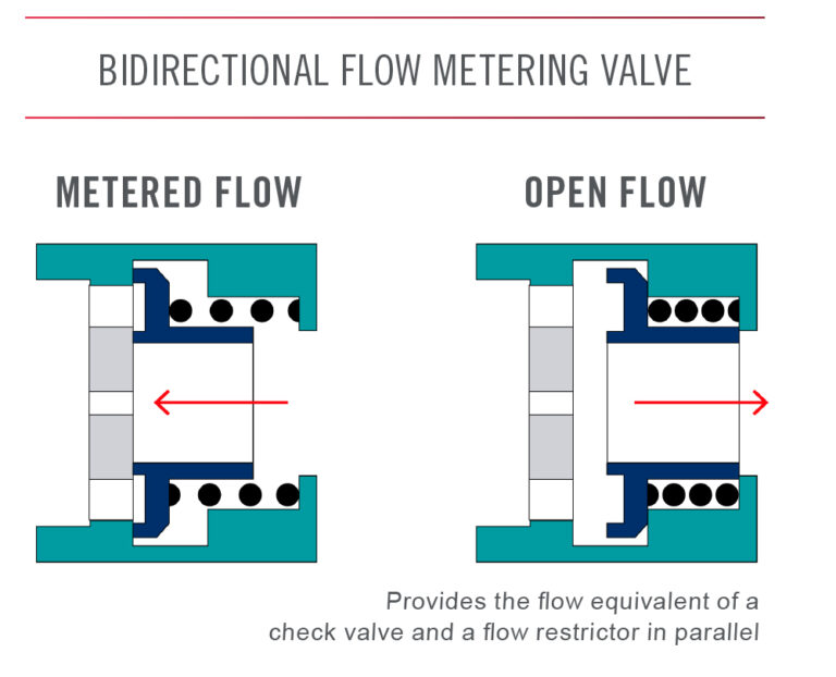
Flow metering valves perform a function similar to a flow restrictor. However, they provide additional functions and are, therefore, more complex. One-way restrictors, or restrictor checks, perform the function of a flow restrictor in one direction and a check valve in the opposite direction. Other valves have mechanically variable restrictions to mitigate viscosity, temperature, or pressure conditions. These valves merit a separate explanation that must be included in this post.
A flow restrictor can serve a few different functions. It is, therefore, essential to select an appropriate flow restrictor to ensure proper functionality during system operation.
The most common function of a flow restrictor is to meter the flow rate of the fluid or gas traveling through it. A simple example is a faucet used to control the speed of water flow into a kitchen sink or out of a showerhead. A flow restrictor is also commonly used within an actuator; it meters fluid and controls the rate of piston travel to influence the speed required to extend or retract. One application for an actuator is the opening and closing of a car door. A flow restrictor can reduce the speed at which the door slams shut.
A flow restrictor may be installed to reduce pressure. For example, a gas may be stored at high pressure to compress it and reduce the required size of the container or tank. A flow restrictor placed at the outlet can precisely reduce pressure and protect or optimize the performance of downstream components. A flow restrictor may also attenuate a system’s pressure pulses. Alternatively, a flow restrictor may be installed in a system to increase upstream or back pressure; this may be done to ensure a certain section of a system has enough pressure to function properly.
A flow restrictor may be required to increase fluid velocity or control the pattern and direction of flow; such a flow restrictor is often referred to as a nozzle. Nozzles may create a smooth, straight stream of flow, which is useful when the fluid is directed at a target. An example is using oil to lubricate gears as they mesh together. A flow restrictor may also spray or atomize fluid, as with a plastic bottle that sprays cleaner on a surface. The atomized spray is beneficial in fuel systems because small droplets of fuel dispersed evenly provide more efficient combustion than a solid flow stream.
The Lee Company developed a simple system of defining the fluid resistance of Lee hydraulic components. Just as the Ohm expresses resistance in electrical engineering, the liquid Ohm or “Lohm” aids with hydraulic and pneumatic computations. When using the Lohm system, designers need not worry about discharge coefficients and dimensional tolerances of drilled holes. These factors are automatically compensated for in the Lohm calculations and are confirmed by testing each component to establish flow tolerances. The resistance to flow of any fluid component can be expressed in Lohms. A 1 Lohm restriction will permit a flow of 100 gallons per minute of water with a pressure drop of 25 psi at a temperature of 80°F. The Lohm formula is derived from Bernoulli’s equation.
Our global sales force of technical sales engineers is available to provide fast, accurate customer assistance and help you find the best solution for your fluid control challenge.
Always verify flow calculations by experiment.
*There are many parameters to consider when determining V-Factor. Click here for more information.


