Achieving precision fluid control in a fluidic system is essential, and careful consideration of variable volume pump connection and mounting is crucial for optimal performance. The successful operation of the pump is intrinsically tied to the overall system design, requiring system designers to account for various pump operations such as purging, fluid aspiration, and fluid dispensing. Exploring fluid connection and mounting configurations for variable volume pumps while incorporating general best practices in the design process ensures that the pump functions as intended within the broader system.
Generally, a variable volume pump must be connected to a fluidic circuit either by using tubing or by directly mounting the pump to a manifold.
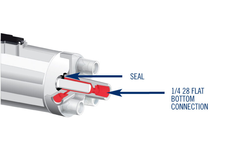
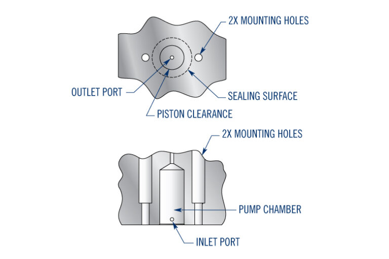
When using a port head configuration, the port head creates the fluid chamber surrounding the piston. This “wet side” is separated from the drive train, sometimes called the “dry side”, by a seal. The standard port head contains two threaded ¼-28 flat bottom boss ports used to connect the system to the pump. Standard port heads are offered in chemically resistant materials, accommodating a wide range of fluids.
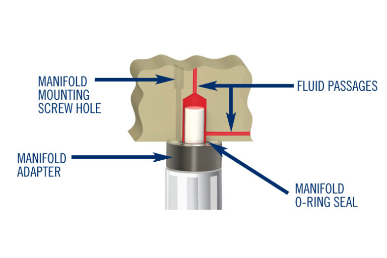
When using a manifold mount configuration, the port head is replaced with a mounting adapter, allowing for the removal of the pump from the manifold without affecting the integrity of the seal. The fluid connection of a manifold mounted variable volume pump is determined by the manifold.
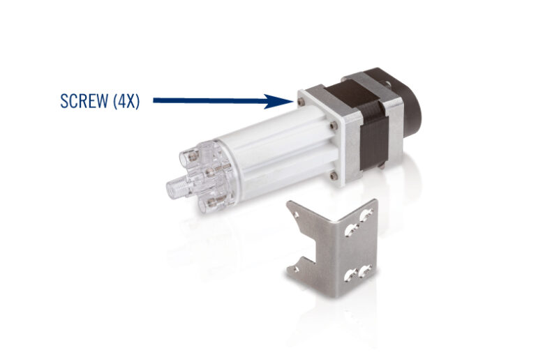
Variable volume pumps can be mounted in a variety of ways. Port head configurations use a mounting bracket, whereas manifold mount configurations have an internal thread for through bolt mounting to a manifold.
When designing your system, consideration must be given to the support of the pump as well as its orientation. The mounting surface needs to be structurally sound to prevent vibration and movement of the pump. Mounting the pump on some surfaces may result in transmission and amplification of normal operating sound. The orientation of the pump may also affect the pump’s ability to purge air. The recommended orientation of the pump is shown below, with the motor facing downward and the port head facing upward.
When selecting a mounting configuration for your pump, note that port head configurations typically ship with a separate mounting bracket. To install this bracket, make sure to remove two of the four screws that connect the housing to the motor and re-install them with the bracket retained. When installing the bracket, it is important to remove only two adjacent screws from the housing at a time. If more than two screws are removed, housing components may shift, resulting in operating problems.
Manifold mount variable volume pumps replace the port head with a manifold adaptor plate. This allows the pump to be installed and removed without degrading pump performance. When installing and removing the pump from a manifold, it is important to maintain cleanliness, so contamination is not introduced into the fluidic system. When designing your system, make sure to refer to the relevant inspection drawing for specific manifold mounting hole specifications.
Thoroughly evaluating fluid connection and mounting configurations available for variable volume pumps will help you make the optimal design choice for your unique application.
Performance is generally dependent on the system within which the variable volume pump is installed. When mapping out a fluidic system, system designers should consider all pump operations including purging, fluid aspiration, and fluid dispensing. Below is a list of general best practices that can help guide your design process.
A variable volume pump’s dispense rate is also dependent on the fluidic system it is designed within. Very high motor speeds may result in high pressures which can damage components or result in splashing during non-contact dispensing (e.g., high droplet exit velocity). Too low a dispense rate can result in “drooling” during non-contact dispensing. Drooling occurs when the droplet does not have enough velocity to cleanly break off from the dispensing tip.
A droplet will need to have enough velocity to “break-off” or separate from the dispensing tip. If it does not, there may be a hanging drop that does not dispense every time. Smaller diameter tips generally increase the fluid’s exit velocity, allowing for a smaller dispense volume without drooling. Non-wetting tips also prevent the fluid from wicking up the dispense tip and creating a hanging drop.
It is important to design the system so the pump is not operating above its maximum recommended speed or within its harmonic range. Either of these cases can result in lost steps or motor signal mismatch, which ultimately will decrease accuracy.
Compliance in a fluidic system is caused by the property of an elastomer to absorb and release energy like a spring. A system consisting of rigid materials without any compliance is frequently described as “hard.” The problem with “soft” systems is that absorbed energy can be imparted back to the fluid in an uncontrolled manner. This can result in both under and over-dispensing. Compliance in a soft system could be caused by very flexible long runs of tubing, such as PVC or silicone thin-walled tubing. Systems can be made harder by using thick-walled tubing, less flexible materials, and shorter lengths of tubing.
Dispense accuracy is impacted by system compliance. Eliminating all compliance may not be a best practice because some system compliance may help to reduce pressure pulsations from the stepper motor-actuated pump. Therefore, tuning and laboratory experimentation may be required to determine the optimum level of compliance for system performance.
In general, the less compliance in a fluidic system, the more accurate variable volume pump operation will be. While flexible tubing and elastomers may seem like the obvious culprit, air bubbles also dramatically affect accuracy. Air bubbles act as small uncontrolled accumulators and can impart unpredictable amounts of energy into the system.
Air can be introduced through several means, including ineffective purging of the system, cavitation, and entrained or dissolved gas.
All air must be purged out of a system prior to dispensing. This includes the pump and all lines leading to and from the pump. The most efficient way to accomplish this is to orient the pump with the port head facing up and the motor facing down.
If the inlet restriction on a variable volume pump is too high, the suction created by the pump during aspiration can lower the pressure inside the port head below the vapor pressure of the fluid, resulting in bubble formation. To avoid cavitation, reduce inlet restriction or reduce the aspiration speed of the pump.
The amount of gas that can be dissolved in a fluid is dependent on pressure and temperature, as well as fluid properties. If a fluid sits for an extended period, gas may come out of the solution in the form of small bubbles. Decreasing pressure also allows more gas to come out of the solution. If this is problematic, the fluid may need to be degassed or a purging sequence may be required at system startup.
It is important to ensure that all air has been removed from the fluid path prior to pump operation. System priming can be completed without additional components or pumps, other than the valves needed for normal operation.
The typical procedure for priming a variable volume pump is to aspirate and dispense fluid repeatedly until there is no more air within the system. This is best accomplished by aspirating slowly, ensuring that more air is not pulled out of the fluid. The fluid dispense rate should be fast, ensuring a higher fluid velocity, which tends to displace bubbles held to passage walls by surface tension.
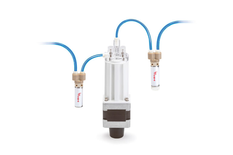
Normal pump orientation is with the motor facing downwards and the port head facing upwards. The inlet of the pump is the side port, and the outlet is the top port. The internal port head geometry has been designed for fast, efficient priming and purging in this orientation. An alternate orientation is to have the pump mounted horizontally with the side port facing up and used as the outlet port. Other mounting options are available; consult The Lee Company for recommendations.
Fittings that are not properly tightened or seated may allow air to enter the system. It is possible that a fitting will pass a pressure check with no leakage and still leak when a vacuum is applied. Inspection of fitting installation during functional testing is recommended to ensure proper sealing.
Variable volume dispense pumps are designed and tested to ensure that they reach their maximum operational life. The operational life of the pump is application-dependent and can be affected by many parameters, such as:
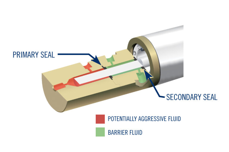
When using fluids that are prone to crystallization, the crystals can damage a seal which can lead to leakage-related failures. Other fluids that contain surfactants, which lower surface tension, tend to slip past the seals of a pump. A secondary seal may be used with the pump to mitigate these issues. Between the seals, an intermediate fluid can prevent crystallization and dilute surfactants, greatly extending the pump’s operational life.
To maximize your variable volume pump’s operational life, consider best practices surrounding dispensing, system compliance, purging, leakage, and operational life.
Partner with The Lee Company and get much more than just a supplier of top-quality fluid control products. Our reliable technical support team is available every step of the way to help you find solutions, maximize productivity, and drive efficiency across your operations. Check out these resources tailored to your industry to learn more.

Our global sales force of technical sales engineers is available to provide fast, accurate customer assistance and help you find the best solution for your fluid control challenge.
Always verify flow calculations by experiment.
*There are many parameters to consider when determining V-Factor. Click here for more information.


