Once optimal performance requirements are identified and environmental factors are considered, the appropriate flow restrictor is selected for the application. It may, however, be difficult to find a solution that meets every requirement. As with most decisions, there are trade-offs that must be considered. Some of these trade-offs are common sense. For example, changing the material from plastic to metal will increase operating or burst pressure capability but will also increase the restrictor’s weight. There are other performance aspects specific to restrictors that may require more careful consideration during the selection process.
During development, it is critical to test the performance of a flow restrictor with the intended fluid under actual system conditions. However, some fluids are expensive, dangerous, or difficult to obtain. For acceptance testing in mass production, it may be more economical to test on a reference fluid and correlate performance to the actual fluid. For example, it may be acceptable to test a restrictor used in a blood analyzer with water rather than the expensive reagents necessary to perform the actual blood analysis. It is also impractical to acceptance test component hardware for every possible combination of system or environmental conditions. The cost and complexity can be reduced while verifying performance by correlating design requirements to an appropriate manufacturing acceptance test. The challenge is that correlations are not perfect and typically require empirical data rather than perfect equations.
The tolerance for a flow rate can sometimes prove to be a challenging design element. There are applications that require very tight tolerances on flow rates. For example, a device used to mix two chemicals may use flow restrictors to create the necessary ratio of different fluids. An incorrect ratio might reduce the efficiency or performance of the mixture; however, the cost to manufacture and validate a tighter tolerance flow restrictor may increase significantly.
It is also worth noting that as the number of individual restrictions increases, it may become more difficult to control the tolerance of the complete flow restrictor. This is the case whether orifices are in series or parallel. The total tolerance in the stack up of multiple orifices in parallel adds further complications. It is described by the following equation:

The tolerance of the higher flow rate orifice will have the greatest impact on the total flow tolerance.
If a single orifice restrictor offers an identical level of restriction to that of a multi-orifice or porous restrictor, the single orifice restrictor will offer a few advantages. It is typically simpler to design and manufacture, smaller in size and lighter in weight, and has a reduced cost. However, the multi-orifice or porous restrictor offers some distinct performance advantages.
The main advantage of multi-orifice restrictors is that they can be used to help mitigate some of the failure modes discussed in more detail below. They offer a larger minimum passage size for an equivalent restriction. This makes them less susceptible to clogging due to debris. In addition, the pressure drop across each individual orifice is less than that across a single orifice. This can reduce the potential for cavitation in liquid flow.
While it is typically easier to manufacture a single orifice restrictor, once the desired orifice size decreases beyond a certain point, it becomes more difficult to manufacture using traditional, low-cost methods. For example, drills may break more easily in extremely small diameters or may not be available at all. Manufacturing tolerances in a small orifice may also result in wider flow tolerances.
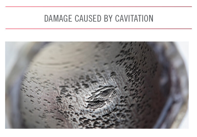
Despite being designed to meet the performance criteria and withstand the environmental factors previously discussed, flow restrictors may become damaged and fail to perform properly in service. It is important to be aware of certain failure modes to ensure the appropriate measures are in place within the system to mitigate the risk of failure. Below are some examples of potential failure modes. This is not a complete list—all potential failure modes for a specific application must be evaluated.
The most common failure mode for a restrictor is damage due to ingestion of foreign material or, simply stated, contamination. Fluids can contain contaminants of various sizes and materials. Such contamination can clog the orifice and stop or lessen the required fluid flow. Excessive, uncontrolled contamination can also erode the orifice. The erosion is typically seen at the edges of the orifice; over time, it may potentially increase the size and flow rate of the orifice. Adequate protection against contamination should be incorporated upstream of the restrictor to reduce the risk of such occurrences. Some flow restrictors may integrate a form of protection as part of the device.
The figure above depicts the cross sections of a single and a multi-orifice system. The pressure graph shows the pressure in a single orifice system dropping below the vapor pressure line and creating a possible choking condition. Whereas, in the multi-orifice system, a much smaller pressure drop is created across each of the orifices; and the individual drops are never below the vapor pressure. Therefore, multi-orifice restrictors are used more frequently when cavitation is a concern in a system.
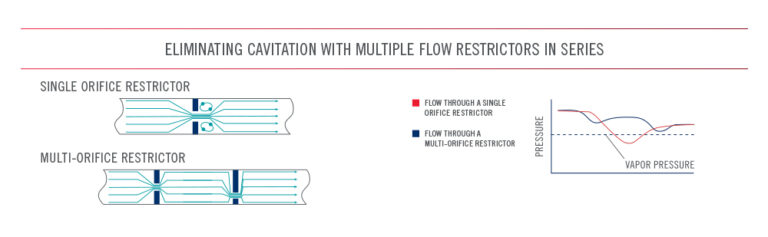
A general rule-of-thumb used to predict the possibility of cavitation in a system is the coexistence of very high upstream pressure and very low downstream pressure. Physical signs of cavitation include abnormal noise, high fluid temperatures, choked fluid flow, and physical erosion of any downstream component near the orifice. Any of these indicators may warrant the installation of a multi-orifice restrictor. In another insight, we describe various types of contamination, walk you through some common signs of trouble, showcase two real-world contamination examples captured in photographs, introduce you to a few solutions, and provide you with basic tips on comparing screens.
Improper installation of a restrictor can result in poor performance. For example, if the flow restrictor is not properly installed, its envelope may become damaged during installation and may lead to an external leakage path. It’s also possible that damage to the restrictor could interfere with its internal components. To avoid these issues, it is critical that restrictor installation instructions are followed closely.
Many industry associations have documented recommendations or requirements for the validation and verification of restrictor performance to ensure safety within a specific system. Compliance with these specifications is usually required by governing bodies and passed down to suppliers of systems and components. The selection of a restrictor must meet industry standards required for the application.
Some examples of industry associations with restrictor guidelines includes:


Our global sales force of technical sales engineers is available to provide fast, accurate customer assistance and help you find the best solution for your fluid control challenge.
Always verify flow calculations by experiment.
*There are many parameters to consider when determining V-Factor. Click here for more information.


