


Sarah Charette
Technical Marketing Manager – Health & Science
Westbrook, CT
See Bio
When evaluating a solenoid valve for a particular application, it is important to ensure that the valve can both remain in state and transition between its de-energized and fully energized states under all potential operating conditions. To accomplish this, a design engineer must identify all forces that will be applied to the valve components over its intended life cycle. They must also determine the worst-case conditions associated with each force both during each state and throughout any transition between states.
By calculating the combination of forces using a force balance equation, an engineer can determine if the valve will behave as intended. The design should include a margin of safety above the worst-case scenario due to potential tolerances associated with different forces. The factor of safety above the force margin may need to be more significant in the following scenarios: if the combination of forces are more complex, if there is a higher potential for failure, or if the result of failure is more severe.
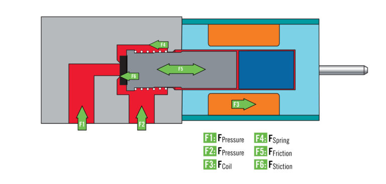
There are several forces at play within a solenoid valve that must be controlled to ensure consistent operation. While these forces are generally present in every solenoid valve, the specific configuration, environment, and function of the valve will determine the level of impact that each force has on operation. When evaluating whether a solenoid valve will function properly within a system, the following forces must be considered:
Use the Lee Product Finder to explore solenoid valves by configuration, porting, actuation type, and performance requirements.
The following scenario helps to explain how an engineer would go about designing a solenoid valve capable of achieving the required force margins based on system requirements and a known valve layout.
In Figure 1, a solenoid valve is required to operate in a system with pressure ranging from 800 to 1000 psia at port P1 venting to the atmosphere at P2. Port P1 has a diameter of 0.025 inches. During a worst-case scenario, the solenoid valve is subjected to a shock equivalent to 50G applied against 0.5 grams of mass in any direction. The force of friction (F5) is a maximum of 0.005 lbf. The forces associated with stiction (F6) and residual magnetism are negligible.
| QUESTION | ANSWER |
| 1. What force must the spring apply to ensure the valve stays closed during the worst-case condition with a factor of safety two times the force? | The force of fluid pressure will work against the force of the spring. In the worst-case condition, we will use the highest operating pressure. The force of the shock will be assumed in the opposite direction of the spring and work against it. To stay closed, the valve will remain in a static position, and the force of friction will not apply. FSpring (F4) = Factor of Safety * (ForceP1 + ForceShock) ForceP1 (F1) = Pressure * Area = 1000 * (π * (0.025/2)2) = 0.491 lbf ForceShock = 0.5 grams * (1 lb / 453.6 grams) * 50 G = 0.055 lbf FSpring = 2 * (0.491 lbf + 0.055 lbf) = 1.092 lbf |
| 2. Using the calculated spring force, what is the required coil force (F3) to open the valve with a 1.5 factor of safety under the worst-case condition? | The force of the spring is working against the force of the solenoid coil (F3). For the valve to open, the force of friction will apply and work against the coil. The fluid pressure is applying force to aid the coil. For a worst-case condition, we will use the lowest operating pressure acting on the smallest valve seat area. We will assume the valve is closed and the plunger is the furthest distance from the pole. The force associated with a shock is not considered in this calculation because a shock only occurs momentarily. FCoil = Factor of Safety * (FSpring + ForceFriction – ForceP1) FSpring = 1.092 lbf (from question 1) ForceFriction (F5) = 0.005 lbf ForceP1 = Pressure * Area = 800 * (π * (0.025/2)2) = 0.393 lbf FCoil = 1.5 * (1.092 lbf + 0.005 lbf – 0.393 lbf) = 1.056 lbf |
System operating conditions help dictate fluid pressure force and the intended end use impacts the resulting environmental forces applied to the solenoid valve. The above scenario represents a typical exercise that an engineer might work through when tailoring a common valve design for a unique system.
A pre-existing valve design will have known forces associated with stiction from the valve seal or friction from the movement of internal components. The spring is designed at a force necessary to hold the components in place while the valve is de-energized. The solenoid coil must then be designed to overcome the forces acting upon the plunger. There are several ways to increase the strength of the magnetic field:
|
Ohm’s Law V (voltage) = I (current) * R (resistance) Based on this law of physics, increasing voltage or decreasing resistance will increase current. |
Force balance equations are important to determine if a solenoid valve is appropriate for its application. As the number of ports, flow paths, and operating conditions become more complex, so do the calculations necessary to develop the valve.
BROWSE OUR SOLENOID VALVES WITH THE LEE PRODUCT FINDER TOOL
The Lee Company designs and manufactures a wide range of valves from miniature plastic pneumatic solenoid valves intended for respiratory therapy applications to high-pressure high-temperature hydraulic solenoid valves used in aircraft, rockets, and satellites operating miles above us. If you are searching for a valve to meet your needs and would like to learn more about solenoid valves offered by The Lee Company, click here or contact a Lee Sales Engineer today.
If you want to learn more solenoid basics, review our related insights below.
Sarah Charette is the Technical Marketing Manager – Health & Science at The Lee Company. In this business development role, she draws upon her extensive engineering knowledge and market expertise to support the diagnostics, medical equipment, and scientific instruments industries. Sarah facilitates the creation of promotional content and product literature and provides technical and market-based training for a global team of sales engineers. She also manages customer relationships and acts as an internal liaison to the Lee product development team, coordinating product design and providing input for new components. She has been with The Lee Company for over 14 years, previously serving as a Product Manager for the Control Valve Group and Applications Engineer. Sarah received a degree in biomedical engineering and Spanish from the University of Rhode Island’s International Engineering Program and an MBA from Quinnipiac University.
Tom Cleveland is the Group Lead Engineer for the Solenoid Group at The Lee Company, where he works closely with sales and manufacturing on new and existing components and applications across multiple industries. In this role, he helps manage, train, and support Product and Project Engineers and provided expert guidance on major customer projects. Tom has been with The Lee Company for 13 years. He received a degree in physics and astronomy from Wesleyan University and a master’s degree in mechanical engineering from the University of New Haven.
Mathew French is the Technical Marketing Manager – Aerospace & Energy at The Lee Company. In this role, he manages customer relationships, leveraging his engineering and market knowledge to help identify business and product opportunities to support the aerospace and defense, space, oil and gas, motorsports, and power generation industries. Mathew oversees the creation of promotional material and educational assets and liaises with the Lee product development team to coordinate custom component design and offer feedback on new products. He also provides product and market training to The Lee Company’s global team of field sales engineers. Mathew has been with The Lee Company for over 19 years, previously serving as a Product Manager for the Solenoid Group and Applications Engineer. He received his mechanical engineering degree from the University of New Hampshire.
Always verify flow calculations by experiment.
*There are many parameters to consider when determining V-Factor. Click here for more information.