Reduce Assembly Costs and Leak Points with Custom Integrated Manifolds.
Manifold material and manufacturing technique selection is driven by chemical compatibility, complexity of the fluidic passages, cost, production volumes, and optical clarity requirements. We’ll work with you to assess which approach is best based on your application needs.
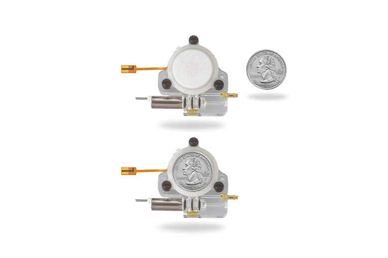
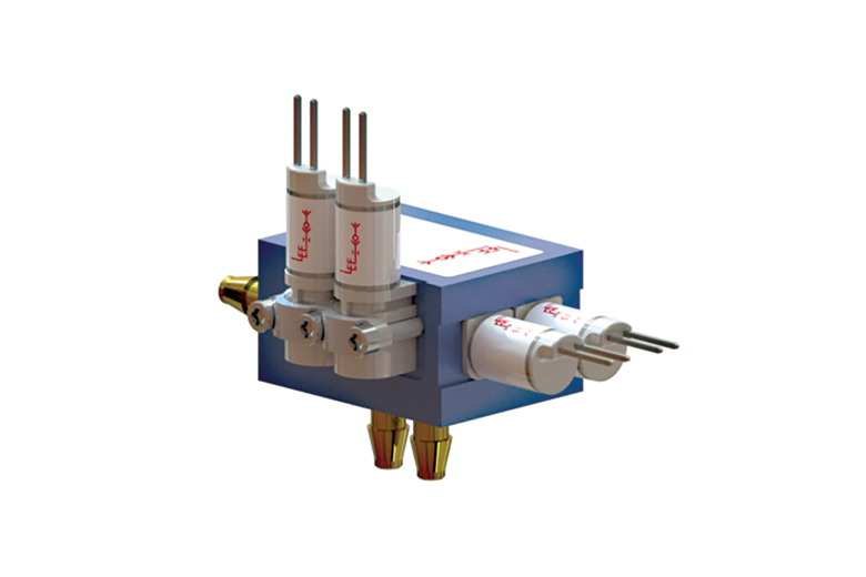
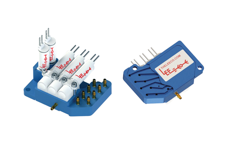
Integrating miniature valves into a manifold using conventional cross-drilled machining is a major step towards reducing tubing and fluid volume. Drilled passages must be straight and construction passageways must be plugged in conventionally machined manifolds. This approach is typically chosen when the valve count is minimal, and the flow paths are simple.
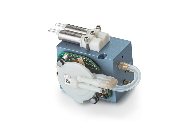
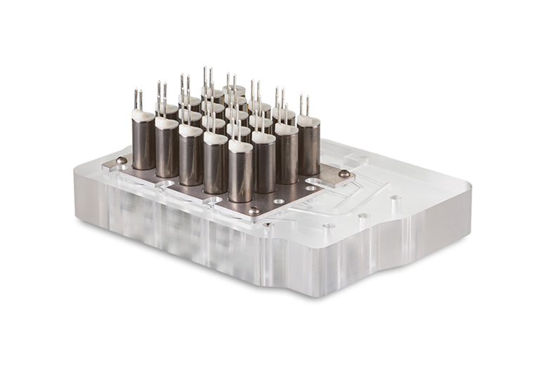
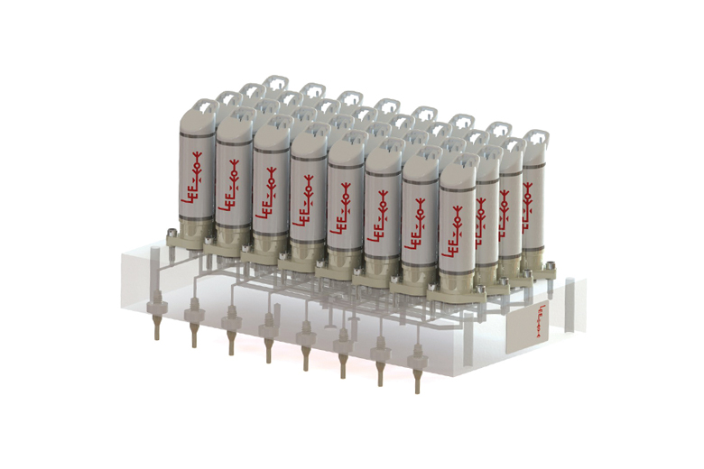
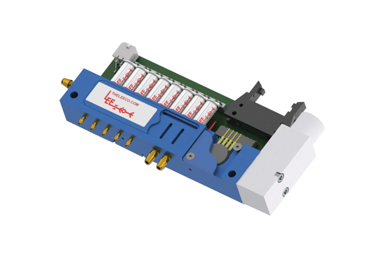
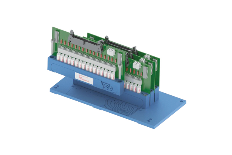
Multi-layer manifolds are ideal for applications with many valves, when the fluidic schematic is more complex, when integrated flow cells are required, or when the output pattern requires tighter spacing than other components allow (e.g., valve center-to-center spacing). These bonded manifolds stack multiple layers of plates containing different machined passages. The different plates are then bonded together either by epoxy, diffusion, or solvent weld.
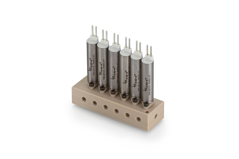
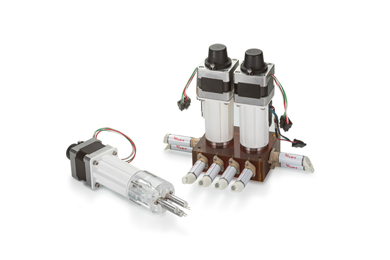
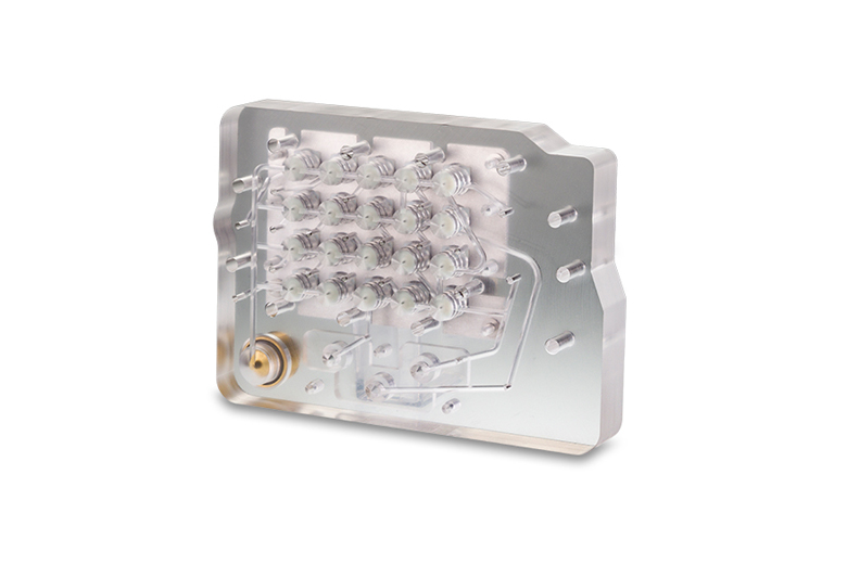
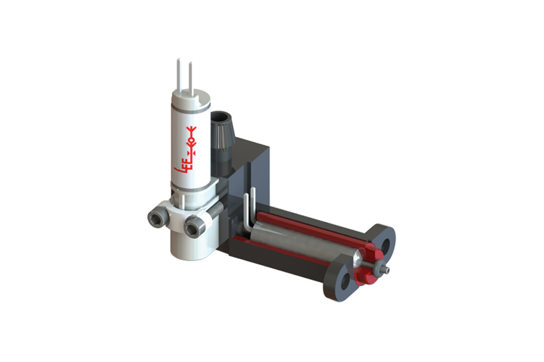
The Ant Farm Technique involves machining a series of intricate flow paths or channels into a face of the manifold. After the machining operation, a plate is bonded over the flow passages to complete the circuit. In complex applications, the channels can be milled into more than one face of the manifold block. This manifold machining technique further reduces the overall manifold size compared to the other technologies. It also enables a modular design where modules of valve manifolds can be mounted onto a base plate via O-ring seals.
Plastic injection molded manifolds can significantly reduce unit cost, reduce size and weight, and they enable unique geometries because they are not beholden to the straight drilled passage limitations of conventionally machined and bonded manifolds. The upfront costs associated with mold design and tooling typically make this option most appropriate for applications with high annual rates of production.
3D printed manifolds can aid in the prototyping phase by allowing you to quickly test various manifold design iterations. As an emerging technology, 3D printing is not yet a practical solution for long-term, robust, leak-proof, chemically inert, production-grade assemblies. However, as the technology continues to evolve, long-term options in a variety of materials – even metals – may become viable manifold solutions. 3D printing and Design For Manufacturability (DFM) considerations during the prototype phase ensure an easy transition to a production solution which uses the manifold technology best suited to your project.
Available manifold materials for each manufacturing technique. Other materials may also be available upon request.
| Material | Chemical Resistance | Conventionally Machined | Multi-Layer Bonded | Ant Farm Bonded | Injection Molded | 3D Printed |
| Various Resins |
Low |
X | ||||
| Stainless Steel |
Low |
X | ||||
| Aluminum | Low | X | X | |||
| PC | Low | X | X | |||
| ABS | Low | X | X | |||
| PBT | Low | X | X | |||
| PVDF | Moderate | X | X | |||
| PMMA (acrylic) | Moderate | X | X | |||
| PSU | Moderate | X | ||||
| PEI | Moderate | X | X | |||
| PEEK | High | X | X |
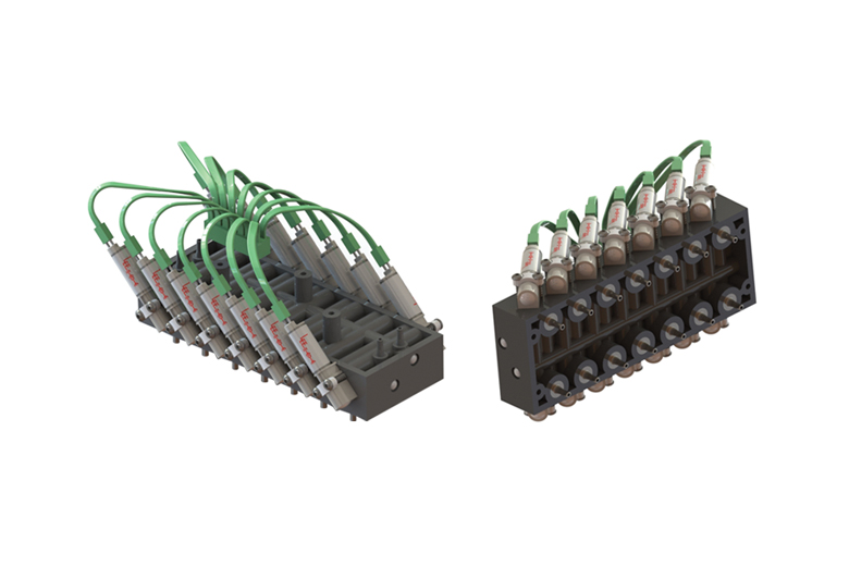
Each manifold assembly is carefully built, tested, and sealed to ensure performance and cleanliness.
Always verify flow calculations by experiment.
*There are many parameters to consider when determining V-Factor. Click here for more information.


